19N10 MOSFET - описание производителя. Даташиты. Основные параметры и характеристики. Поиск аналога. Справочник
Наименование прибора: 19N10
Тип транзистора: MOSFET
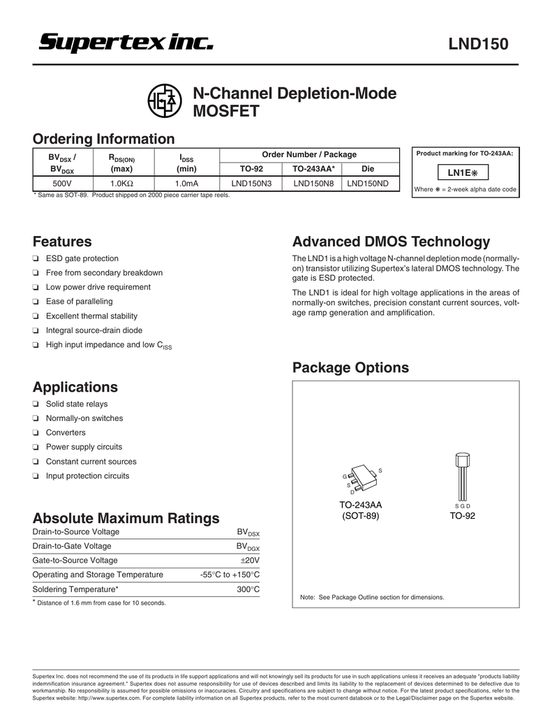
DMOS FET Package: (blank) = 3-lead SOT-23 Environmental: G = Lead (Pb)-free/RoHS-compliant Package Media Type: (blank) = 3000/Reel for an SOT-23 Package; XX Package - X - X Environmental Media Type Options 2018 Microchip Technology Inc. DS20005797A-page 13 Information contained in this publication regarding device. On this channel you can get education and knowledge for general issues and topics. Description: The Microchip DN2625 is a low threshold depletion-mode (normally-on) MOSFET transistor utilizing an advanced vertical DMOS structure. The design combines the power handling capabilities of a Bipolar Transistor with the high input impedance and positive temperature coefficient of MOS.
Полярность: N
Sonar free. download full version. Максимальная рассеиваемая мощность (Pd): 178 W
Предельно допустимое напряжение сток-исток |Uds|: 100 V
Предельно допустимое напряжение затвор-исток |Ugs|: 25 V
Максимально допустимый постоянный ток стока |Id|: 15.6 A

Максимальная температура канала (Tj): 150 °C
Время нарастания (tr): 150 ns
Выходная емкость (Cd): 165 pf
Сопротивление сток-исток открытого транзистора (Rds): 0.078 Ohm
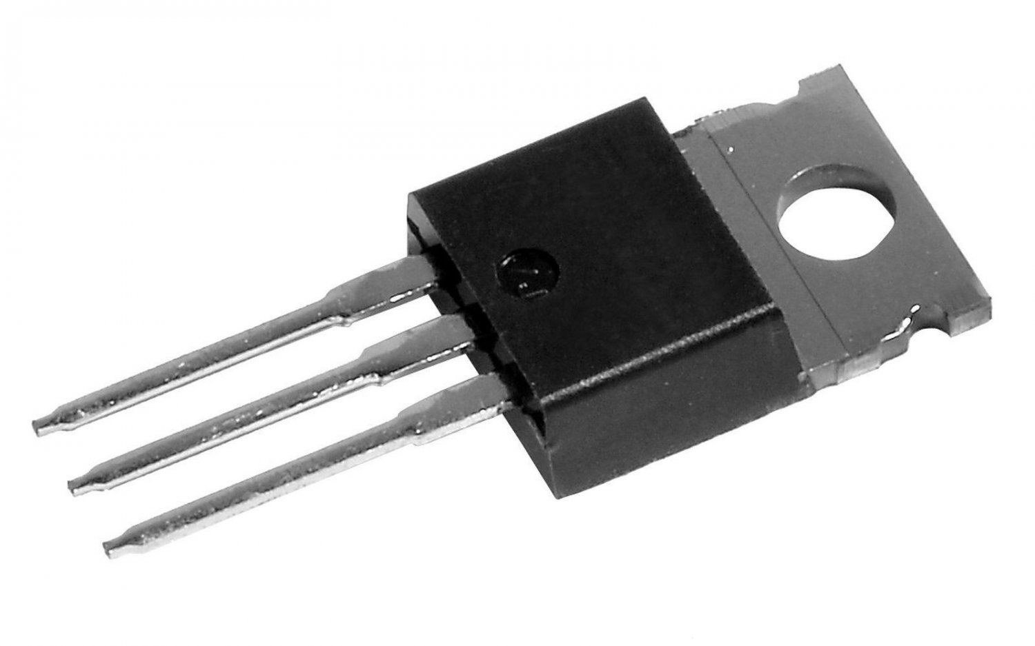
Тип корпуса: TO-3PTO-251TO-252TO-220TO-263
19N10 Datasheet (PDF)
0.1. fqd19n10ltf fqd19n10ltm fqd19n10l fqu19n10l.pdf Size:688K _fairchild_semi
January 2009QFETFQD19N10L / FQU19N10L100V LOGIC N-Channel MOSFETGeneral Description FeaturesThese N-Channel enhancement mode power field effect 15.6A, 100V, RDS(on) = 0.1 @VGS = 10 Vtransistors are produced using Fairchilds proprietary, Low gate charge ( typical 14 nC)planar stripe, DMOS technology. Low Crss ( typical 35 pF)This advanced technology has been
0.2. fqpf19n10l.pdf Size:616K _fairchild_semi
August 2000TMQFETQFETQFETQFETFQPF19N10L100V LOGIC N-Channel MOSFETGeneral Description FeaturesThese N-Channel enhancement mode power field effect 13.6A, 100V, RDS(on) = 0.1 @VGS = 10 Vtransistors are produced using Fairchilds proprietary, Low gate charge ( typical 14 nC)planar stripe, DMOS technology. Low Crss ( typical 35 pF)This advanced technology h
0.3. fqb19n10ltm.pdf Size:611K _fairchild_semi
August 2000TMQFETQFETQFETQFETFQB19N10L / FQI19N10L100V LOGIC N-Channel MOSFETGeneral Description FeaturesThese N-Channel enhancement mode power field effect 19A, 100V, RDS(on) = 0.1 @VGS = 10 Vtransistors are produced using Fairchilds proprietary, Low gate charge ( typical 14 nC)planar stripe, DMOS technology. Low Crss ( typical 35 pF)This advanced tec


0.4. fqb19n10tm.pdf Size:926K _fairchild_semi
October 2008QFETFQB19N10 / FQI19N10100V N-Channel MOSFETGeneral Description FeaturesThese N-Channel enhancement mode power field effect 19A, 100V, RDS(on) = 0.1 @VGS = 10 Vtransistors are produced using Fairchilds proprietary, Low gate charge ( typical 19 nC)planar stripe, DMOS technology. Low Crss ( typical 32 pF)This advanced technology has been especially
0.5. fqpf19n10.pdf Size:581K _fairchild_semi
August 2000TMQFETQFETQFETQFETFQPF19N10100V N-Channel MOSFETGeneral Description FeaturesThese N-Channel enhancement mode power field effect 13.6A, 100V, RDS(on) = 0.1 @VGS = 10 Vtransistors are produced using Fairchilds proprietary, Low gate charge ( typical 19 nC)planar stripe, DMOS technology. Low Crss ( typical 32 pF)This advanced technology has been
0.6. fqd19n10tf fqd19n10tm fqd19n10 fqu19n10.pdf Size:678K _fairchild_semi
January 2009QFETFQD19N10 / FQU19N10100V N-Channel MOSFETGeneral Description FeaturesThese N-Channel enhancement mode power field effect 15.6A, 100V, RDS(on) = 0.1 @VGS = 10 Vtransistors are produced using Fairchilds proprietary, Low gate charge ( typical 19 nC)planar stripe, DMOS technology. Low Crss ( typical 32 pF)This advanced technology has been especial
0.7. fqp19n10l.pdf Size:626K _fairchild_semi
August 2000TMQFETQFETQFETQFETFQP19N10L100V LOGIC N-Channel MOSFETGeneral Description FeaturesThese N-Channel enhancement mode power field effect 19A, 100V, RDS(on) = 0.1 @VGS = 10 Vtransistors are produced using Fairchilds proprietary, Low gate charge ( typical 14 nC)planar stripe, DMOS technology. Low Crss ( typical 35 pF)This advanced technology has
0.8. fqp19n10.pdf Size:591K _fairchild_semi
August 2000TMQFETQFETQFETQFETFQP19N10100V N-Channel MOSFETGeneral Description FeaturesThese N-Channel enhancement mode power field effect 19A, 100V, RDS(on) = 0.1 @VGS = 10 Vtransistors are produced using Fairchilds proprietary, Low gate charge ( typical 19 nC)planar stripe, DMOS technology. Low Crss ( typical 32 pF)This advanced technology has been es
0.9. 19n10.pdf Size:246K _utc
UNISONIC TECHNOLOGIES CO., LTD 19N10 Power MOSFET 15.6A, 100V N-CHANNEL POWER MOSFET DESCRIPTION The UTC 100V N-Channel enhancement mode power field effecttransistors (MOSFET) are produced by UTCs planar stripe, DMOS technology which has been tailored especially in the avalanche and commutation mode to minimize on-state resistance, provide superior switching performance
Другие MOSFET.. 2N7002ZT, UF3055, UTD3055, 12N06, 12N06Z, 15N06, 12N10, 15N20, 2SK163, 22N20, 25N06, 25N10, 30N06, 50N06, 60N06, 60N08, 6N10.
Список транзисторов
Обновления
MOSFET: CEZ3R04 | CEZ3P08 | CES2322 | CEB93A3 | CEF9060N | CEB6086 | CEN2321A | CEN2307A | CEM9288 | CEM6056L | CEM4052 | CEM2192 | CEU25N02 | CED25N02 | CEU20N02 | CED20N02DMOS vs VMOS vs LDMOS | Difference between DMOS, VMOS, LDMOS
This page compares DMOS vs VMOS vs LDMOS and mentions difference between DMOS, VMOS and LDMOS.It mentions DMOS structure, VMOS structure and LDMOS structure.
DMOS basics | DMOS structure
DMOS stands for Double-Diffused MOS.The device is widely used in switching applications requiring high voltage and high frequency behavior.The other applications of DMOS are Inkjet printheads, automobile control electronics, power supplies etc.
The figure-1 depicts DMOS structure. Following are the properties of DMOS device.
• The DMOS device uses a double diffusion process.
• The p-region and the n+ source regions are diffused through commonwindow. This is defined by edge of the gate.
• The p-region is being diffused deeper compare to n+ source.
• The surface channel length is defined as the lateral diffusion distancebetween the p-substrate and the n+ source.
• The breakdown voltage and on-resistance are two important parameters of DMOS device.
• Due to high voltage and high frequency characteristics it is similar to BJT.
• The very high breakdown voltage is achieved due to lightly doped drift region between Drain and channel regions.
• The n-drift region thickness should be as thin as possible in order to achieve lower drain resistance.
VMOS basics | VMOS structure

VMOS stands for Vertical Metal Oxide Silicon.The device has V-shaped gate region.The devices are used for applications requiring medium powers such aspower amplifiers and switching.
The figure-2 depicts VMOS structure. Following are the properties of VMOS device.
• It consists of shaped groove.
• Due to source at top and drain at bottom, the current flows vertically rather than horizontally.
• V shaped gate makes cross-sectional area of source to drain path larger.Hence lower ON resistance of the device can be achieved which allows much higher power.
• The gate consists of metallised area over the V groove which controls current flow in P-region.
• VMOS structure is more complex compare to traditional FET device.This makes it more expensive.
LDMOS basics | LDMOS structure
LDMOS is asymmetric power MOSFET device.It is designed for applications requiring lower on-resistance and higher blocking voltage.
Dmos Mosfet
In LDMOS channel current is being controlled by vertical electric field (E).This E-field is induced by gate and lateral field which exists between S (Source) and D (Drain).In LDMOS device, channel is determined by three parameters viz. gate length, drain diffusion and source diffusion.
The device is fabricated using diffusion and ion implantation processes.Initially p-type region is constructed.Later shallow p+ and n+ regions are being formed.The source and drain contact regions are created from n+ regions.The p+-region contacts with the p-type body. This is shorted to source part.This will eliminate body effect.The figure-3 depicts LDMOS structure.
Refer Advantages and disadvantages of LDMOS>> for more information.
MOSFET and BJT related links
MOSFET vs IGBT➤
PNP Transistor Vs NPN Transistor➤
BJT vs FET➤
JUGFET vs MOSFET➤
Depletion MOSFET vs Enhancement MOSFET➤
MOSFET Fabrication Technology➤
MOSFET vs BJT-Difference between MOSFET and BJT➤
Application Note-MOSFET as switch and amplifier➤
Difference between NMOS vs PMOS➤
Dmos Mosfet Diagram
What is Difference between
Dmos Mosfet Tutorial
difference between FDM and OFDM
Difference between SC-FDMA and OFDM
Difference between SISO and MIMO
Difference between TDD and FDD
Difference between 802.11 standards viz.11-a,11-b,11-g and 11-n
OFDM vs OFDMA
CDMA vs GSM
RF and Wireless Terminologies
Dmos Mosfet Testing
Share this page
Dmos Power Mosfet
Translate this page
